
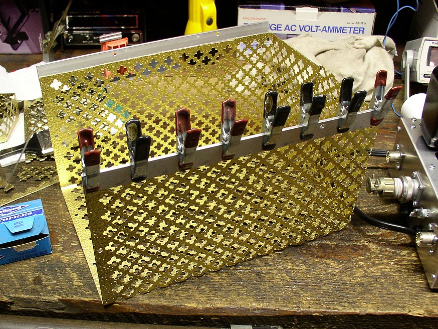
| Gluing The Front and Back Sections of the Cage: The cover for the amplifier serves two main purposes: 1. Most importantly, the cover prevents contact with the dangerous high voltages inside the amplifier. 2. The cage prevents RF harmonics from escaping from the amplifier. The cover could be made from any metal shielding material, but I had a couple of pieces of expensive gold anodized aluminum left over from some household remodeling. Neither piece was big enough by itself, but together they would do the job. The two halves could have been screwed or riveted together, but I opted to glue them together with epoxy glue, which would result in an almost invisible seam. In this photo, the two halves have been bent into the proper shape and cut to the proper dimensions. They have been glued together with epoxy glue and are clamped with alligator clips and other clamps until the glue sets up. |
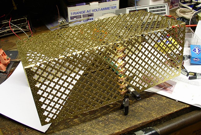 Click on the image for a larger view. Click here for a super detailed view. |
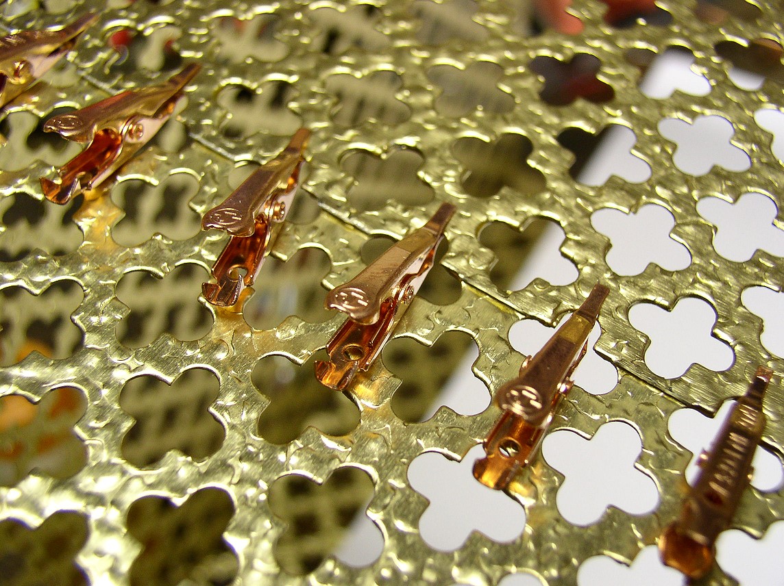
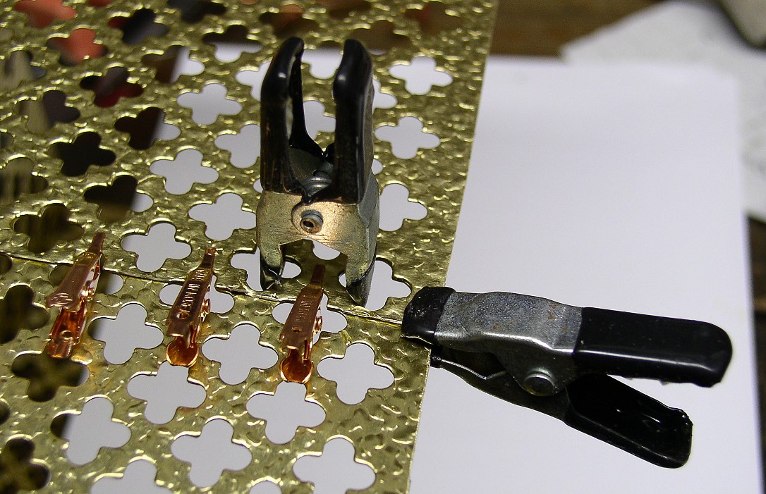
| Close-Up of Small Clamps on Cage Top: In this picture you can see the small alligator clips used to clamp the two halves together while the glue set. These alligator clips were purchased from Radio Shack, and make excellent clamps for small gluing projects. |
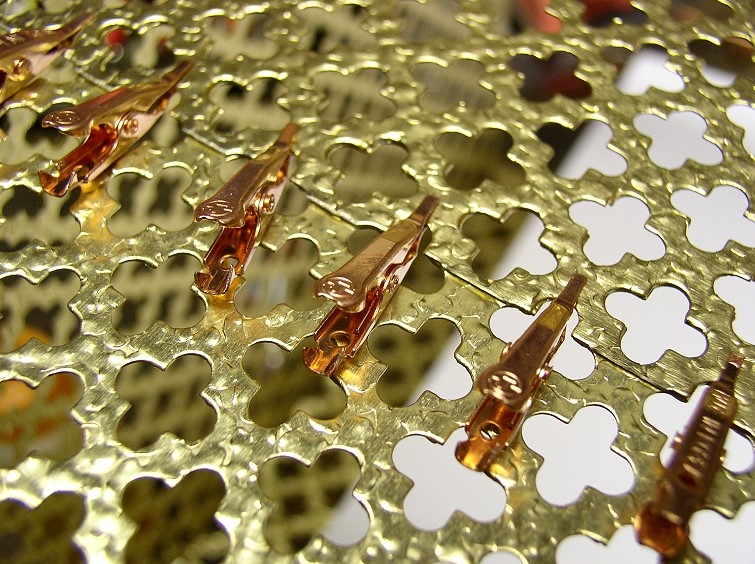 Click on the image for a larger view. Click here for a super detailed view. |
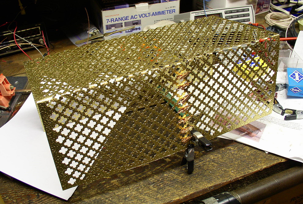
| Close-Up of Clamps on Cage Side: The sides of the cage required more force to keep them together, so conventional clamps were used to hold them. |
Click on the image for a larger view. Click here for a super detailed view. |
| Gluing on the Side Rails: Aluminum side rails fitted to the cage were used to attach the cage to the chassis. Once again, screws or rivets could have been used to fasten the rails to the cage, but I used epoxy glue instead. In this picture, clamps are holding the rail in place while the glue sets up. |
 Click on the image for a larger view. Click here for a super detailed view. |
 Back to Dr. Greg Latta's
Electrical Engineering and Amateur Radio Pages
Back to Dr. Greg Latta's
Electrical Engineering and Amateur Radio Pages
 If you have any questions or
comments, you can send E-Mail to Dr. Greg Latta at
glatta@frostburg.edu
If you have any questions or
comments, you can send E-Mail to Dr. Greg Latta at
glatta@frostburg.edu
This page is under constant revision. Please check back often.