
Click on the image for a larger view.
Click here for a super detailed view.
Plate Tank Coil Details:
The Main Inductor:
When retro-building a piece of ham radio equipment, some of the most difficult
parts to find or make are the inductors. It is often impossible to buy the
correct conductor new or to even find it at a hamfest fleamarket. As a result,
the builder is often forced to make the inductor from scratch.
The original amplifier plans called for 18 turns of #16 wire, 2" in
diameter, spaced 10 turns per inch, and tapped at 1 1/8, 5 1/8, and 11 1/8
turns from the plate end for the main inductor. According to the original
plans, a piece of B & W #3907-1 coil stock would fill the bill. The builder
only had to buy the coil stock, cut it to length, and tap it at the proper
places. Ah, those were the good old days.....Nowadays, however, it is very
difficult to find B & W coil stock, and, if found, it is very expensive.
The solution is to make the inductor yourself from scratch.
Where to Get Materials:
Fortunately for us, coil forms are readily available at the hardware store in
the form of ABS plumbing pipe and couplings. These are ideal for use as coil
forms. For the main tank coil, a white ABS coupling was found with an outside
diameter of 2".
For the wire use #16 bare copper wire. If you can't find any bare #16 wire,
just buy some solid #16 MTW (machine tool wire) and remove the insulation.
| Grind Indentations On The Coil Form: The trick in winding the coil is to get the turns to stay in place. My solution was to use a Dremel tool to grind small indentations in the coil form every 1/10" on one side of the form. On the other side of the form, grind an identical set of indentations but offset them by 1/20" from the first set of indentations. The indentations should be sized so that the wire will sit in them and not slip out. The photo at right is an extreme close-up of the tank coil where you can see the indentations: |
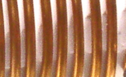 Grind indentations onto the the coil form with a Dremel tool to help keep the turns in place. |
| Install Machine Screws and Wind the Coil: Next, mount a couple of #6 or #8 machine screws on the coil form as seen in the photo to the right. These should be mounted so that 18 turns of wire will fit between them. Be sure you have enough wire for the 18 turns, then fasten one end of the wire to one of the screws on the coil form. Tie the other end of the wire to a firm support like a work bench or door knob. Pull the wire as tight as you can and then wind the wire onto the form, making sure that the wire seats into the indentations you made in the form. Finish by tieing the wire off on the other machine screw. |
 Mount machine screws on the coil form and wind the coil. |
| Glue the Turns In Place: Once the turns are tightly wound, you can adjust them to even out the spacing. Then place a bead of epoxy glue along one side of the coil to hold the turns in place. The bead of glue can be seen in the photo at right. |
 Glue the turns in place with epoxy glue |
| Make The 10m Coil: The 10m coil consists of 4 1/4 turns of #14 wire, 1 3/16" diameter, 5/8" long. If you can't find any bare #14 wire, just buy some solid #14 MTW (machine tool wire) and remove the insulation. You may have to hunt around to find something that has a diameter of 1 3/16" to serve as a temporary form. One option is to find a woodworker with a lathe that can turn a dowel down to the right size. Wind the turns close together, and then pull them apart until the coil is the correct length. Be sure to leave the ends long so you can connect them into the circuit. Important note: the 10m coil is part of the inductance on all of the bands, so you must include the 10m coil even though you don't plan to operate on 10m |
 Make the 10m coil, even if you don't plan to operate on 10m. |
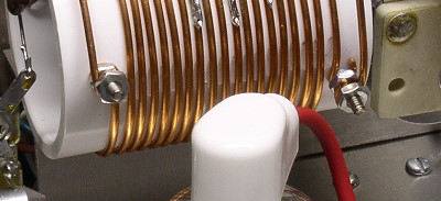
| Determine the Correct Tap Location for Each
Band: You can use my coil tap locations if you like, but the best way to find the correct tap for each band is by experiment. After the main coil and 10m coil are mounted, as can be seen at the right, and the rest of the transmitter is completed, use a wire with a small alligator clip to clip onto the coil at the approximate location of the tap. (Be sure the alligator clip doesn't short to adjacent turns! Grind down the alligator clip if necessary.) Use my tap locations as your initial starting points. Operate the transmitter into a dummy load and wattmeter on the desired band and adjust the tuning and load controls for maximum output. Start with as little drive as possible (detune the input circuit if necessary to reduce the drive) until you can resonate the circuit, then you can increase the drive and power output. Try different tap locations until you find the one that gives the most output. (The correct tap must be determined with the transmitter running full output). A word of caution here: High voltage is present in this amplifier. Always unplug the amplifier before adjusting the taps or making any other adjustments! |
Click on the image for a larger view. Click here for a super detailed view. Use my tap locations, or, better yet, experimentally determine the proper tap locations. |
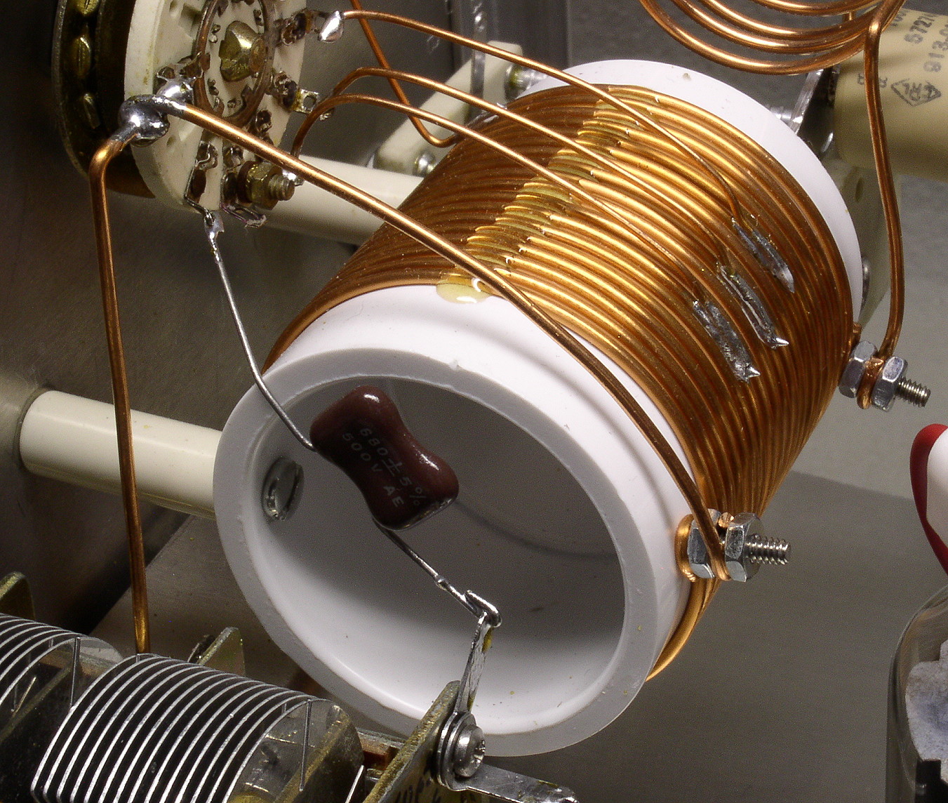
| Solder the Taps to the Coil Once you are certain of the correct tap positions, you can solder the taps in place. First use a Dremel tool to grind a small flat on the coil wire at the desired location. Then tin the flat with solder. (Be careful not to overheat the coil!). Use a pair of pliers to flatten the end of the tapping wire, and then tin that as well. You can then hold the tapping wire against the flat spot on the coil and solder it in place. One again, be careful not to overheat the coil. |
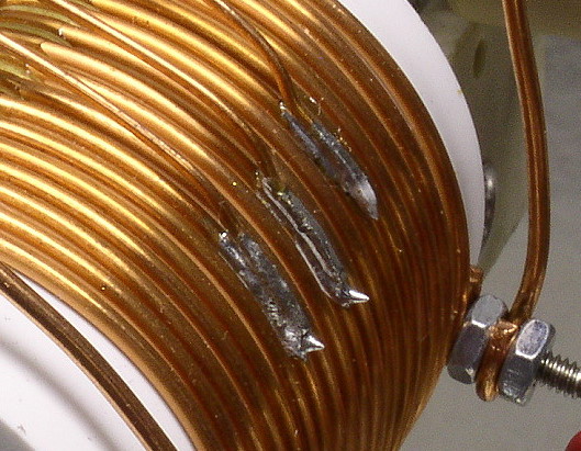 Click on the image for a larger view. Solder the taps in place. |
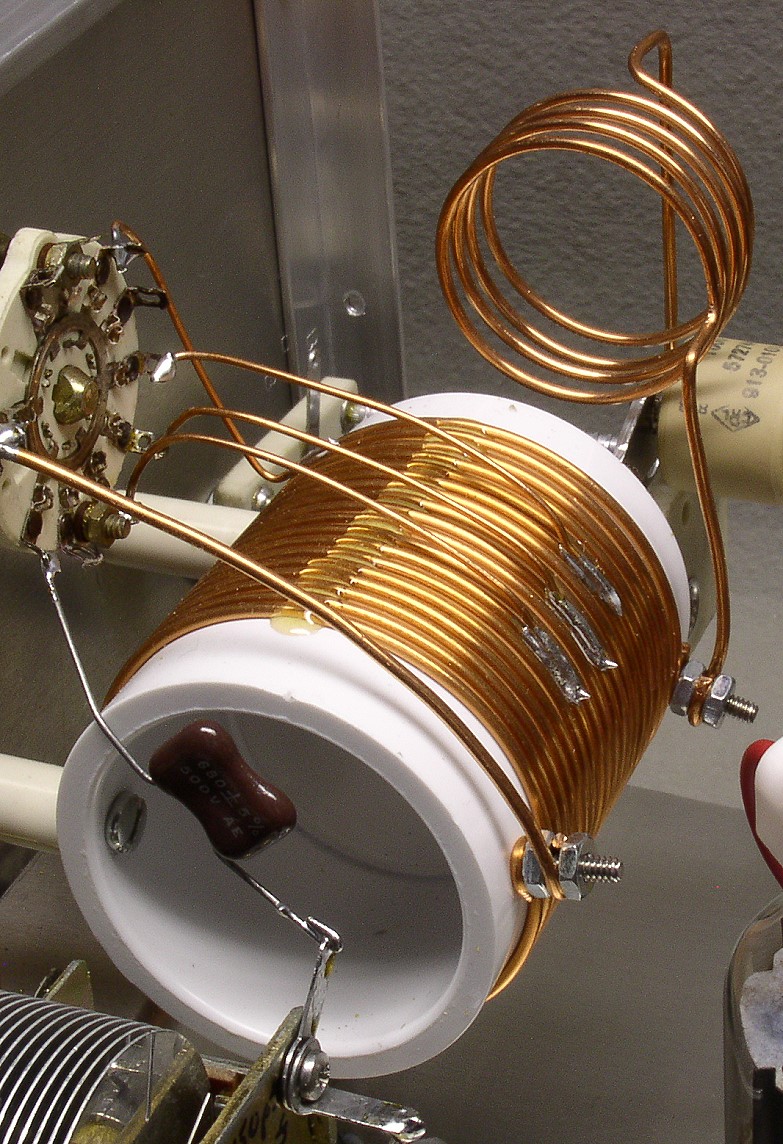
| Close-Up Of The Completed Tank Coil: In this view of the completed tank coil you can see how the machine screws are attached to the coil and how the coil is mounted on ceramic stand-off insulators on the back side of the front panel. The bandswitch can be seen at the top left in the picture. Though the band switch has sufficient positions for all of the ham bands from 160-10m, several of the positions were left unconnected. Since the amplifier was only going to be used on 80, 40, 30, 20, and 15m, only those connections were made to the coil.. The 80m tap is the machine screw on the front of the coil, followed by the 40, 30, and 20m taps, which are soldered to the right side of the coil. The 15m tap is soldered to the left side of the coil, towards the back. |
 Click on the image for a larger view. Click here for a super detailed view. Close-up of the completed tank coil |
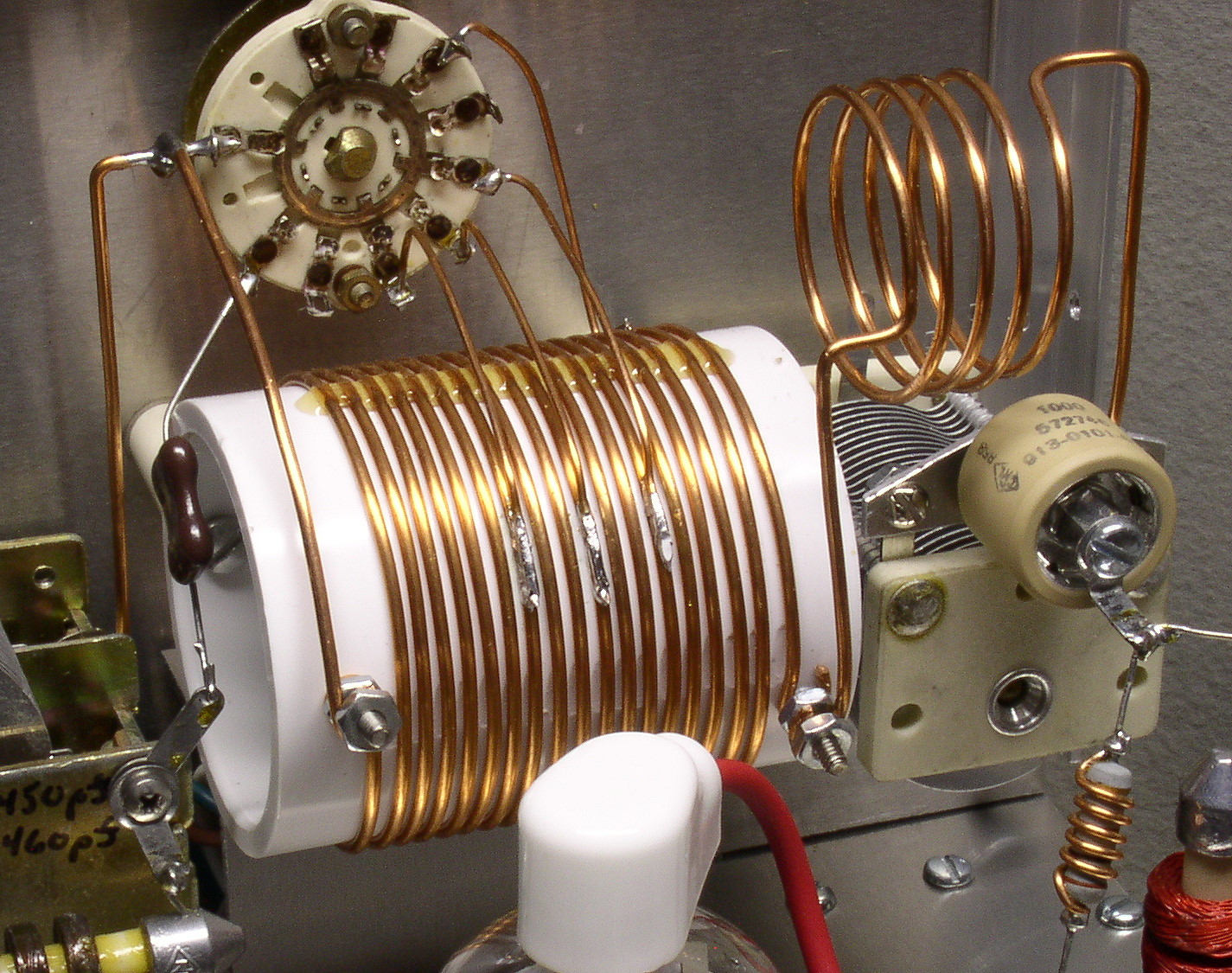
| My Tap Locations: This photo clearly shows where the taps are for each of the band, as I experimentally determined them. My tap locations were as follows: 80m - entire coil (i.e. left end in the photo) 40m - 7 1/8 turns from the left end 30m - 10 1/8 turns from the left end 20m - 13 1/8 turns from the left end 15m - 1 1/2 turns from the right end |
 Click on the image for a larger view. Click here for a super detailed view. Close-up of the completed tank circuit, showing the location of my taps |
 Back to Dr. Greg Latta's
Electrical Engineering and Amateur Radio Pages
Back to Dr. Greg Latta's
Electrical Engineering and Amateur Radio Pages
 If you have any questions or
comments, you can send E-Mail to Dr. Greg Latta at
glatta@frostburg.edu
If you have any questions or
comments, you can send E-Mail to Dr. Greg Latta at
glatta@frostburg.edu
This page is under constant revision. Please check back often.