
The 6146B amplifier uses a tuned link to feed the input signal to the grid of the tube, as shown in the schematic at right. Capacitor C1 tunes the secondary L2 to resonance. |
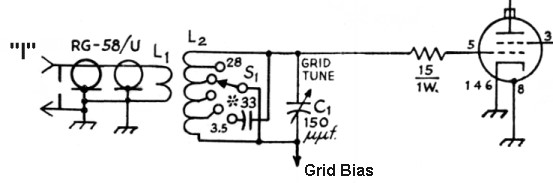 |
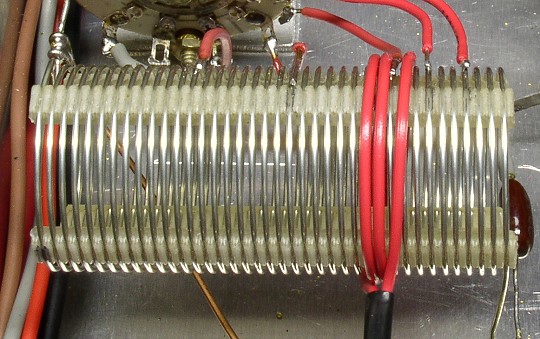
Input link L1 consists of 3 turns of insulated hookup wire
wound around the 10th turn from the grid end of L2, as shown in the photo at
right. |
Click on the image for a larger view. Click here for a super detailed view. |
The secondary coil L2 consists of 37 turns of #20 wire, 1
inch in diameter, spaced 16 turns to the inch (B&W/Miniductor/Airdux
#3015). According to the schematic for a double 6146B amplifier in the 1967
ARRL Handbook ( from which the design of the input circuit was taken), taps
were to be placed at 3, 6, 9, and 25 turns from the grid end of the coil.
However, since this amplifier used a single 6146B rather than a pair, and since
it would also cover the new WARC bands, such as 30m and 17m, the original tap
points were only used for starting estimates. The actual tap points were
determined by experiment, as explained below. |
 Click on the image for a larger view. Click here for a super detailed view. |
To determine the actual tap points, a special type of
alligator clip was used to make a temporary connection. These alligator clips
can be purchased at Radio Shack and they are wonderful for making temporary
connections in tight places, since they have narrow, flat jaws. They are also
excellent for use as gluing clamps in many other applications. (They were used
as clamps when building the high voltage
cage, as shown in the photo at right.) |
 |
The final input coil assembly can be seen in the photo at right. The grid end of the coil is to the left. From left to right the taps are for 10m, 15m, 20m (between the turns of L1), 30m, and 40m. The entire coil is used on 80m. |
 Click on the image for a larger view. Click here for a super detailed view. |
 Back to Dr. Greg Latta's
Electrical Engineering and Amateur Radio Pages
Back to Dr. Greg Latta's
Electrical Engineering and Amateur Radio Pages
 If you have any questions or
comments, you can send E-Mail to Dr. Greg Latta at
glatta@frostburg.edu
If you have any questions or
comments, you can send E-Mail to Dr. Greg Latta at
glatta@frostburg.edu
This page is under constant revision. Please check back often.