| 6146 Amplifier - Main Page and Exterior Photos | Plate and 10m Tank Coil Construction Details |
| Interior Photos of the Finished Amplifier | Construction of Input Coils L1 and L2 |
| Amplifier Schematic Diagrams and Circuit Descriptions | High Voltage Cage Construction |
| Power Supply Schematic Diagrams and Circuit Descriptions | 6146B Beam Power Tube and Data Sheets |
| Construction Photos | Typical Operating Conditions |
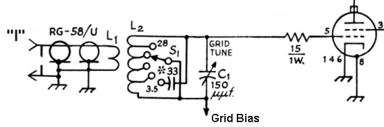
| Input/Grid Circuit: In a grid driven amplifier it is necessary to match the low impedance of the driving transmitter (typically 50 ohms) to the high impedance input of the tube (typically several thousand to several million ohms). The signal from the input jack travels via RG-58 coaxial cable through relay K1 to the input link L1, which consists of three turns of insulated hookup wire on coil L2. L2 is tuned to resonance by the grid tuning capacitor C1. The transformer action of L1 and L2 steps up the voltage, matching the low impedance of the driving transmitter to the high impedance input of the tube. If extra driving power is available, as is the case with the 6CL6 transmitter, the grid tuning control is used as a drive level control, and is tuned off resonance to reduce the drive to an acceptable level. Grid bias is fed into the bottom of L2 and travels through L2 and the 15 ohm resistor to the grid of the tube. The 15 ohm resistor helps to load the grid and provide additional stability. Since capacitor C1 carries the negative grid bias, C1 must be insulated from ground and an insulated coupling must be used on its shaft. |
 |
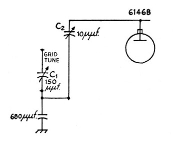
| Neutralization Circuit and
Procedure: Though screen grid tubes are inherently more stable than triodes and may in some cases be used without neutralization, good amplifier design demands that they be neutralized, especially in a multiband amplifier. The neutralization is accomplished by intentionally feeding some of the output signal back to the input out of phase. This cancels the positive feedback that occurs between the plate and control grid of the tube. Capacitive feedback is used, since the amount of feedback will then be independent of frequency. The bottom of the input circuit is not grounded for RF, but is slightly above ground due the the 680 pf capacitor. A small variable capacitor C2 is connected from the plate of the output tube to the top of the 680 pf capacitor. These two capacitors then form a capacitive voltage divider that is frequency independent. Capacitor C2 controls the amount of negative feedback. Note that both sides of C2 are above ground for DC and RF so that C2 must be mounted on a standoff insulator, even if it has an insulated shaft. Since one side of C2 is connected to B+ and the other to negative grid bias, adjustments to C2 must be made very carefully to avoid shock or shorting out the plates of the capacitor. In practice, the amplifier is operated on the 20m band and C2 is adjusted so that the dip in plate current that occurs while plate tuning capacitor C3 is tuned through resonance occurs simultaneously with maximum output. Extreme care must be made while making this adjustment, since B+ is on during the adjustment procedure. An insulated, all plastic screwdriver should be used to adjust C2. |
 |
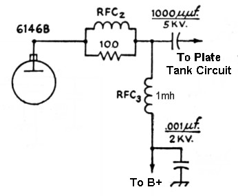
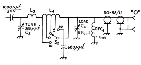
| Plate Tank Circuit: The plate tank circuit is a pi-network that matches the high impedance of the plate to the low impedance of the antenna. At the same time the circuit filters out undesired harmonics from the output signal. The signal from the plate enters through the 1000 uuf plate coupling capacitor at the upper left in the schematic. The 300 uuf plate tuning capacitor in combination with the plate tank coils L3 and L4 tunes the amplifier to resonance. The band switch varies the inductance of the tank coil L4, and the 910 uuf load capacitor adjusts the network for the best impedance match. The 2.5 mH RF choke performs two important functions: If the plate coupling capacitor should fail and short, the RF choke will short circuit the plate supply, blowing the power supply fuse. This will prevent the plate voltage from appearing on the antenna, a very dangerous situation. The choke also prevents any DC voltage from appearing across the load capacitor, lowering the voltage it is required to handle. After passing through the matching circuit the signal then travels through RG58 coaxial cable to relay K1 and the output connector. |
 |
| Meter Circuit: Metering the plate, screen, and grid currents of an RF amplifier is an important method of monitoring amplifier operation. The best way, if space and money permit, is to use a separate meter for each element, as was done in the Wingfoot 813 Amplifier. Separate meters provide a simultaneous view of all amplifier currents in a single glance. They meters are, however, expensive, and take up a lot of space. The usual method is to use a single meter that can be switched to read different currents. The original design called for a meter with a full scale sensitivity of 5 mA. However, since I had a perfect surplus meter with a full scale sensitivity of 50 uA, this was used instead. The ARRL handbook contains equations on how to determine the proper shunt resistance for a given meter. That value was used as a starting point, but then the meter was placed on the test bench and the shunt value (22 ohms in parallel with 1000 ohms=21.5 ohms) experimentally determined so that the meter read full scale when exactly 5 mA was flowing through the circuit, as measured on a high accuracy digital meter. The two pole three position rotary switch S3 connects the meter to the desired tube element. X=control grid, Y=screen grid, Z=plate. |
 |
| Grid Metering Resistor: To meter the grid current a 100 ohm resistor is placed in series with the control grid to carry current when the meter isn't switched in. When the meter is switched in to read grid current it is placed in parallel with the 100 ohm resistor, and most of the grid current flows through the meter, since the meter and its shunt have much lower resistance than the 100 ohm resistor. Since some current does still flow through the 100 ohm resistor, the indicated current is slightly lower than the actual grid current, but the difference is not important. |
 |
| Screen Metering Resistors: In the screen grid circuit very accurate metering was desired. Since the expected screen current was about 15 mA, a full scale reading of 25 mA was selected. To meter the screen current, the meter was configured as a voltmeter to read the voltage drop across a 200 ohm resistor placed in series with the tube screen. The screen current creates a voltage drop across the resistor, which is then read by the meter. The meter multiplier resistor (820 ohm and 15k ohm in parallel=777 ohm) was carefully chosen so that the meter read exactly full scale when 25 mA flowed to the screen. |
 |
| Plate Metering Resistors: In the plate circuit very accurate metering was also desired. Since the expected plate current was about 150 mA, a full scale reading of 250 mA was selected. To meter the plate current, the meter was configured as a voltmeter to read the voltage drop across a 20 ohm resistor placed in series with the tube plate. The plate current creates a voltage drop across the resistor, which is then read by the meter. The meter multiplier resistor (1k ohm and 20k in parallel=952 ohm) was carefully chosen so that the meter read exactly full scale when 250 mA flowed to the plate. |
 |
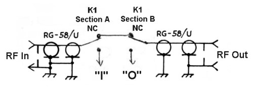
| Transmit/Receive/Bypass
Circuit: When an RF amplifier is used with a transceiver, it is necessary to bypass the amplifier during receive periods. In this amplifier sections "A" and "B" of relay K1 handle the transmit/receive switching. (Section "D" is used for bias switching.) When the coil of relay K1 is not activated (amplifier "Off" or in "Standby") the normally closed (NC) contacts of relay sections "A" and "B" connect the amplifier input jack directly to the output jack, bypassing the amplifier. When the relay coil is activated (amplifier in "Operate") the input jack is connected to the input of the amplifier "I" and the output jack is connected to the output of the amplifier "O". When used with a straight transmitter such as the 6CL6 transmitter the mode switch is left in the operate position during use. |
 |
| Bias Circuit: The amplifier bias circuit applies adjustable regulated bias to the 6146B control grid. The use of regulated bias results in improved linearity, important when the amplifier is used for SSB service. To avoid the expense of a separate power transformer, a filament transformer is run in reverse to step some of the filament voltage from the main power transformer back up to 117 V. This is then run through a simple half-wave rectifier CR1 and then filtered by the 47 uf capacitor. The OA3 gaseous regulator tube then regulates the output of the supply to 75 V. The regulated 75 V is then applied to the 10k bias adjust potentiometer. In "Standby" mode the coil of relay K1 is not activated, and one end of the 10k potentiometer is left unconnected. This applies the full 75 V output of the bias supply to the 6146 grid cutting off the tube. During "Operate" mode, the coil of relay K1 is activated, and the end of the 10k potentiometer is grounded, reducing the bias to the value selected by the bias adjust potentiometer. In actual operation the bias control is adjusted so that the idle plate current is 15 mA. During CW operation, when the amplifier is driven into grid current, the resistance between point X2 and ground also functions as a grid leak, providing additional bias on the tube. The 100 ohm resistor is used to meter the grid current, and radio frequency choke RFC1 allows the grid bias to pass through to the tube while preventing any RF in the input circuit from reaching the bias supply. |
 |
 Back to Dr. Greg Latta's
Electrical Engineering and Amateur Radio Pages
Back to Dr. Greg Latta's
Electrical Engineering and Amateur Radio Pages
 If you have any questions or
comments, you can send E-Mail to Dr. Greg Latta at
glatta@frostburg.edu
If you have any questions or
comments, you can send E-Mail to Dr. Greg Latta at
glatta@frostburg.edu
This page is under constant revision. Please check back often.