
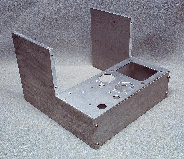
| Chassis and Power Supply Deck: The first step in the restoration/build was to completely disassemble the chassis and clean it. Since the chassis is a bolt together design, this was not difficult. Chassis panels were thoroughly scrubbed with Soft Scrub, which is really a very fine cleanser. This removed all of the old dirt and left a beautiful sheen finish on the aluminum. The parts were removed from the power supply deck (the power supply was not wired) and the deck was cleaned and new holes were made to accommodate the new components. |
 Click on the image for a larger view. Click here for a super detailed view. |
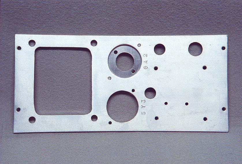
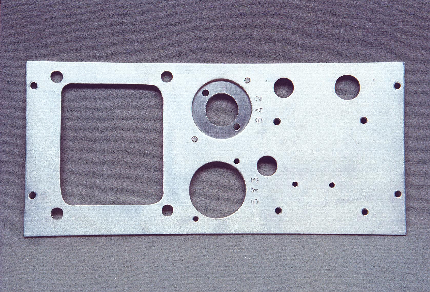
| Power Supply Deck: As received, the power supply components were not wired. These were removed and the power supply sub-chassis ("deck") was thoroughly cleaned. In this photo, a hole that originally held a twist-lock electrolytic filter capacitor has been filled in to accommodate a tube socket that will hold one of the 7-pin VR tubes. The hole for the other VR tube socket has not yet been made. Holes have also been drilled for the filter choke and for terminal strips that will be used to support the various components. The large hole at bottom holds the 5Y3 rectifier tube socket. Tube sockets are labeled by stamping the tube number into the chassis with a set of 1/8" metal stamps. Though the top socket is labeled "0A2", it was later decided to use an "0B2" tube instead. |
 Click on the image for a larger view. Click here for a super detailed view. |
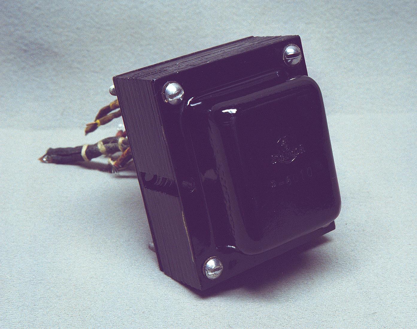
| Power Transformer: After removal from the chassis, the power transformer (a Stancor model P-8010) was cleaned and painted. To do this, the transformer bolts and covers were carefully removed, then cleaned and painted with gloss black spray enamel. The core was then masked with masking tape and the sides sprayed with the same enamel. The bolts were scrubbed with soft scrub to shine the heads. The entire unit was then reassembled. The result is what you see in the photo. |
Click on the image for a larger view. Click here for a super detailed view. |
| Completed Power Supply: After the power supply deck was completed, the power supply was wired and tested. Though solid state rectifiers could have been used rather than the 5Y3, the 5Y3 was retained for authenticity. A choke was also included in the filter circuit, since this would lower the ripple. Two VR tubes in series were used. Originally, the plan was to use an 0A2 and an 0B2 for a regulated screen voltage of 258 volts, but later it was decided to use two 0B2 regulators, which dropped the screen voltage to 216 volts. This made no change in the transmitter output, but reduced the oscillator screen current by a substantial amount. Click here for the power supply schematic and circuit description. Click here for a bottom view of the finished power supply. |
 Click on the image for a larger view. Click here for a super detailed view. |
| Unrestored Front Panel - Rear View: In this view, the oscillator turret assembly has been removed from the original front panel, leaving only the output tank circuit and the key jack. The original front panel was pretty much a mess. Knobs were too close together, the key jack was in a bad location, and there were unused holes in the panel. |
 Click on the image for a larger view. Click here for a super detailed view. |
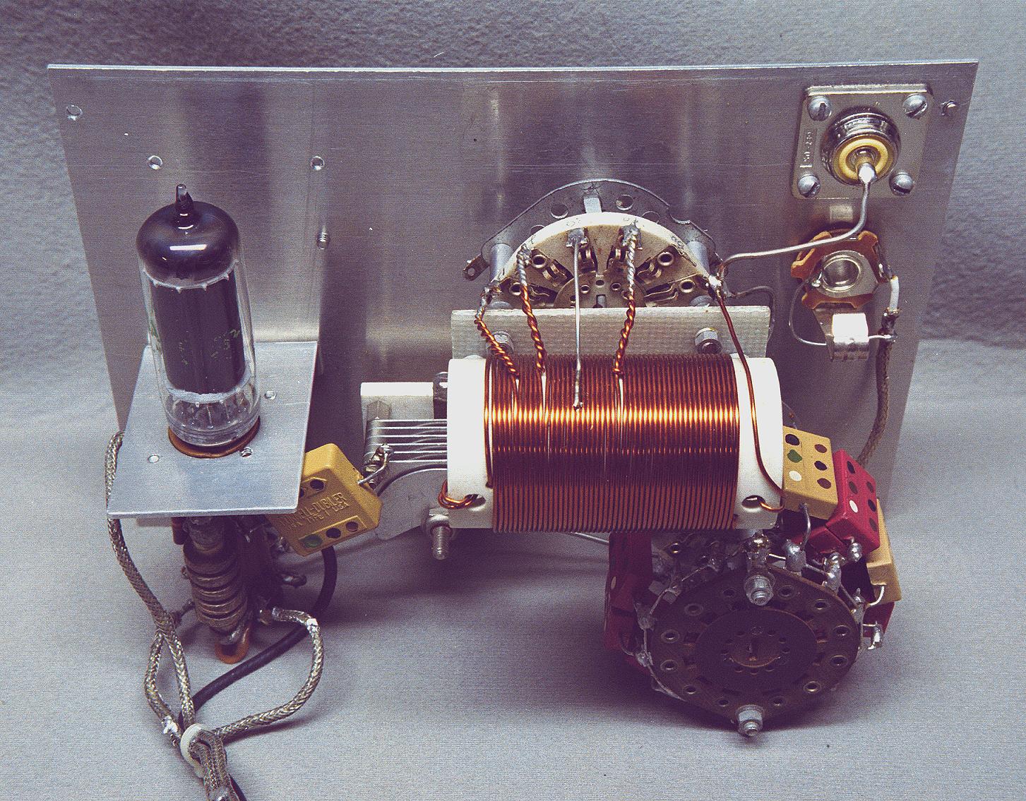
| Restored Front Panel - Rear View #1: Because of many problems with the original front panel, a new front panel was machined. This is a photo of the completed transmitter wired and mounted on the new front panel. (In this photo, the front panel is upside-down so that more components are visible.) The plate tuning capacitor (white) is visible at top center, and the oscillator turret assembly, which contains most of the components, is visible at right. The plate tank coil is at bottom, and the loading capacitor switch assembly is on the left. |
 Click on the image for a larger view. Click here for a super detailed view. |
| Restored Front Panel - Rear View #2: This is the same as the previous photo, but with the new front panel right-side-up. The 6CL6 oscillator tube is on the left, and the output jack is at upper right. The bandswitch and tank coil taps are visible in the middle of the photo.Click here for a view with all of the components labelled. |
 Click on the image for a larger view. Click here for a super detailed view. |
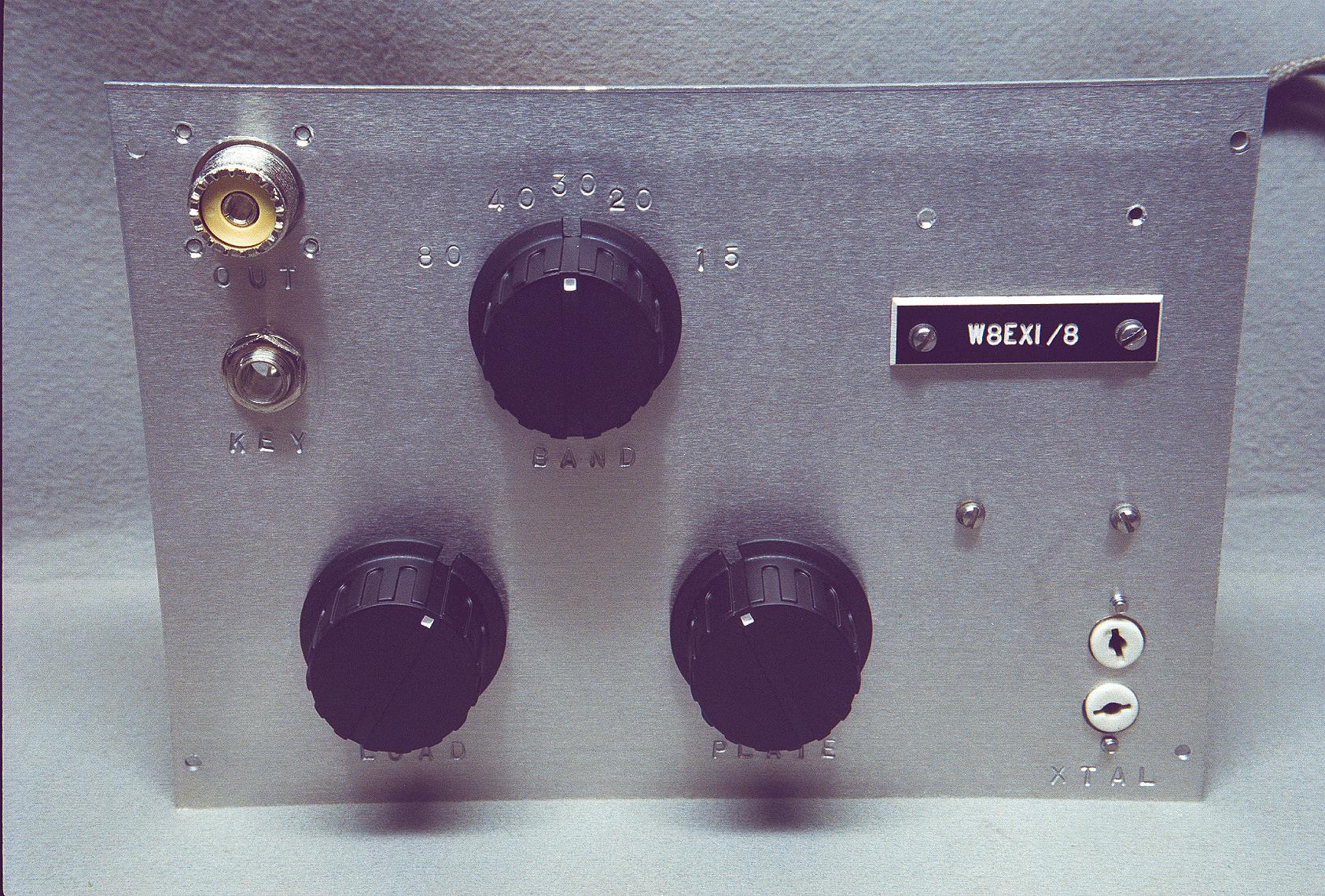
| Restored Front Panel: This is a front view of the new front panel. The panel was machined out of brushed sheet aluminum obtained at a surplus metal shop in Akron, Ohio. The sheet metal comes with a protective plastic coating that protects it during the various machining operations. The coating is only removed at the very end. After the coating is removed, the functions of various knobs and jacks are stamped into the panel with a set of 1/8" metal stamps. The original transmitter had a plastic label on the front panel with the original builder's call (Jim Trutko, W8EXI) on it. This was retained, and holes were drilled above it to accommodate a label with "AA8V" that will be added in the future. |
 Click on the image for a larger view. Click here for a super detailed view. |
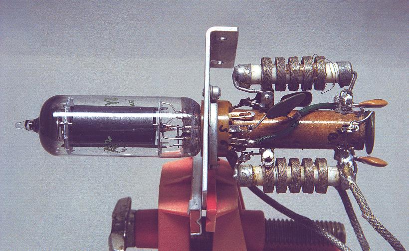
| Turret Assembly During Construction - View #2: All of the oscillator components (except for the power supply and final tank circuit) are mounted on a single turret assembly that is integrated with the tube socket. Normally used for circuits in early vacuum tube computers, turrets are rarely used in amateur radio equipment, and this is the only one I have ever seen. This circuit was largely rewired, and the original feedback capacitors were replaced with different values. (These are the red molded silver mica capacitors on top of the turret.) The cathode RF choke can be seen at the top and the plate RF choke is on the bottom. The shielded wires carry filament voltage, regulated screen voltage, and plate voltage to the oscillator. |
 Click on the image for a larger view. Click here for a super detailed view. |
| Turret Assembly During Construction - View #1: This is a view from the other side of the turret. In this view it is easy to see that the turret assembly is actually an integral part of the tube socket. The tube socket is mounted on an "L" shaped bracket which then attaches to the back of the front panel. Notice also that I have labeled some of the tube pins with a Sharpie magic marker to assist in wiring and possible later troubleshooting. |
 Click on the image for a larger view. Click here for a super detailed view. |
 Click here for pictures and information on the Wingfoot
VFO 2E26 Exciter
Click here for pictures and information on the Wingfoot
VFO 2E26 Exciter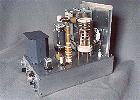 Click here for pictures and information on the Wingfoot
813 Amplifier
Click here for pictures and information on the Wingfoot
813 Amplifier Back to Dr.
Greg Latta's Electrical Engineering and Amateur Radio Pages
Back to Dr.
Greg Latta's Electrical Engineering and Amateur Radio Pages
 If you have any questions or
comments, you can send E-Mail to Dr. Greg Latta at
glatta@frostburg.edu
If you have any questions or
comments, you can send E-Mail to Dr. Greg Latta at
glatta@frostburg.edu
This page is under constant revision. Please check back often.