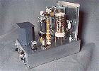

Introduction:
The tune up procedure for the 6CL6 transmitter is the same procedure that is
used for virtually all transmitters with a pi-network output. The procedure is
best done using an RF output meter connected to the antenna line, but can also
be done satisfactorily with a milliammeter/multimeter in series with the key to
measure cathode current. The preferred method is to use an RF output meter.
Tune Up Using An RF Output Meter (Preferred Method):
1. Insert a crystal and connect a dummy load or antenna and RF output meter to
the transmitter.
2. If connected to an antenna, make sure the frequency is clear by listening
for a while and then calling QRL? and then listening some more. (Remember, a
station that you cannot hear may be sending to another station.)
3. Set the antenna loading capacitor to maximum capacity (plates fully meshed).
4. Key the transmitter and adjust the plate tuning control for maximum output.
5. Unmesh the antenna loading capacitor slightly and repeak the output with the
plate tuning control. You should now have more output.
6. Continue doing this until the output no longer increases.
Your goal is the highest capacitance setting of the loading control that still
gives you maximum output.
Tune Up Using A Milliammeter/Multimeter (50mA-250mA Full Scale) To
Measure Cathode Current:
1. Insert a crystal and connect a dummy load or antenna to the transmitter.
2. Connect a milliammeter (about 50mA-250mA full scale) in series with the key.
An analog meter is preferred, as it will make seeing the dip much
easier.
3. If connected to an antenna, make sure the frequency is clear by listening
for a while and then calling QRL? and then listening some more. (Remember, a
station that you cannot hear may be sending to another station.)
4. Set the antenna loading capacitor to maximum capacity (plates fully meshed).
5. Key the transmitter and adjust the plate tuning control for dip in the
cathode current.
6. Unmesh the antenna loading capacitor slightly and redip the cathode current.
The minimum cathode current should now be higher and the dip should be broader.
7. Continue doing this until the cathode current at the dip no longer
increases.
Your goal is the highest capacitance setting of the loading control that still
gives you a dip in the cathode current.
Adjusting the Plate Tuning Capacitor For Best Keying:
The setting of the plate tuning capacitor affects the quality of the
transmitter keying. You may be able to obtain better keying (less chirp) by
slightly detuning the control from resonance (the position the the gives the
most output or minimum cathode current).
With the transmitter connected to a dummy load and tuned up, listen to the
keying in a quality receiver that has the input shorted to prevent
receiver overload. It is very important to make sure that you aren't
overloading the receiver. While sending CW, try detuning the plate tuning
control slightly from resonance and see if this improves the keying. The effect
on the keying is not symmetrical. Detuning the plate tuning control to the high
side of resonance has a different effect than detuning it to the low side of
resonance.
What you are doing is sacrificing some output to improve the keying. How much
output you sacrifice is up to you. As always, it is a compromise. Even if you
sacrifice as much as 20% of your power output (for example, dropping from 5
watts output to 4 watts output) the difference in signal strength will only be
1dB, which won't be noticeable to the other operator. However, the improvement
in keying will be noticeable to the other operator. You want quality,
not quantity.
Every crystal will behave differently, so you will have to find the best
setting for every crystal that you use.
 Click here for pictures and information on the Wingfoot
VFO 2E26 Exciter
 Click here for pictures and information on the Wingfoot
813 Amplifier
 Back to Dr.
Greg Latta's Electrical Engineering and Amateur Radio Pages
 If you have any questions or
comments, you can send E-Mail to Dr. Greg Latta at
glatta@frostburg.edu
This page is under constant revision. Please check back often.