Tom Green's (K7MDO) Version of the 6CL6 Transmitter
It's heartening to know that others have found these pages useful. The ultimate compliment is when I receive news that someone else has built the transmitter and has it on the air. On this page you can find pictures and information on these other versions of the transmitter.
In November of 2011 Tom Green (K7MDO) finished building his 6CL6 transmitter and was kind enough to send me some photos. I thought it would be helpful to show how someone else put the transmitter together. If you have any questions for Tom, you can e-mail him at chknlips@msn.com
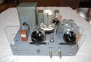
| Front View: In his version of the transmitter, Tom used a clear plexiglass front panel. This lets you see right through to all of the parts on the top of the chassis. Tom also used a single 0D3 regulator tube rather than the two 0B2 regulator tubes that I used in my design. This places 150 volts on the screen grid, rather than 300 volts, resulting in significantly less transmitter output. However, this may improve the keying, as it will result in less crystal current. Tom's tank coil (the white coil in the middle of the photo) is from a surplus TCS-12 transmitter. It will run on 40m and 20m, but does not have enough turns to run on 80m. |
 Click on the image for a larger view. Click here for a super detailed view. |
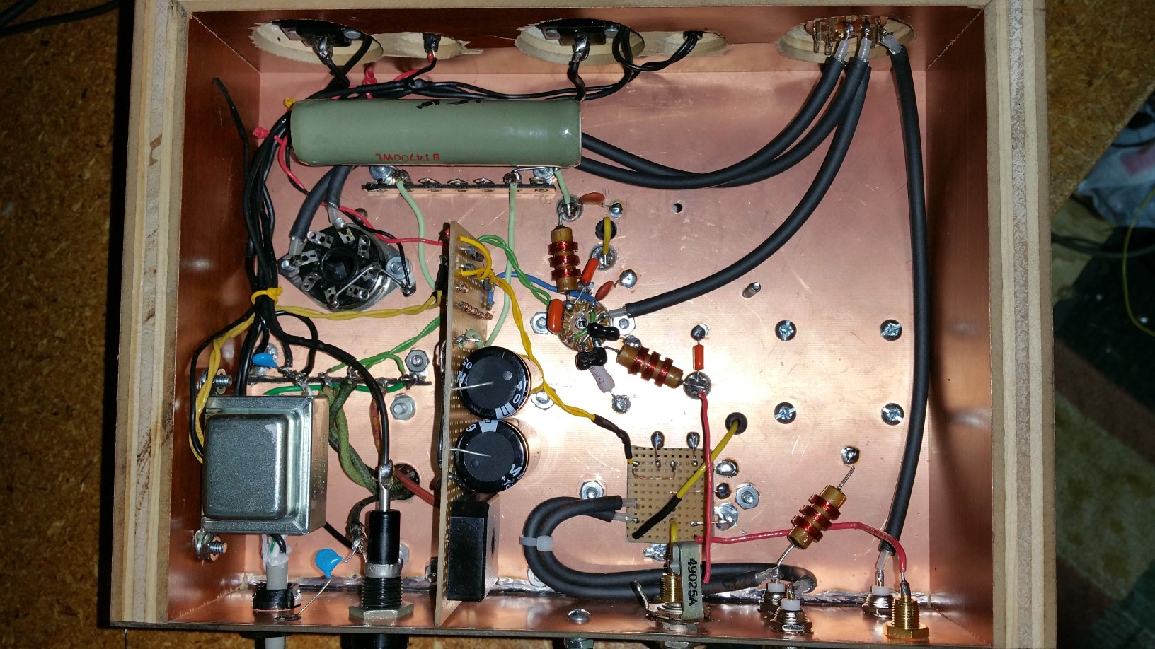
| Bottom View: This is a bottom view of Tom's transmitter. In this view the front panel is in the top of the photo. The power supply takes up the bottom of the chassis in the photo. Connections to the power transformer are through the large circular cutout in the chassis at the lower left. To the right of that are the connections to the filter choke (small circular opening) and filter capacitors. To the right of the filter choke is the VR tube socket. Tom included a transmit/receive relay in his transmitter. This can be seen at the bottom right. The 6CL6 tube and associated components are in the upper left in the photo. |
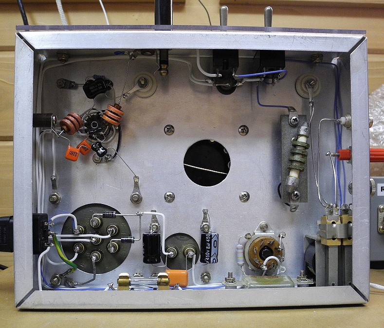 Click on the image for a larger view. Click here for a super detailed view. |
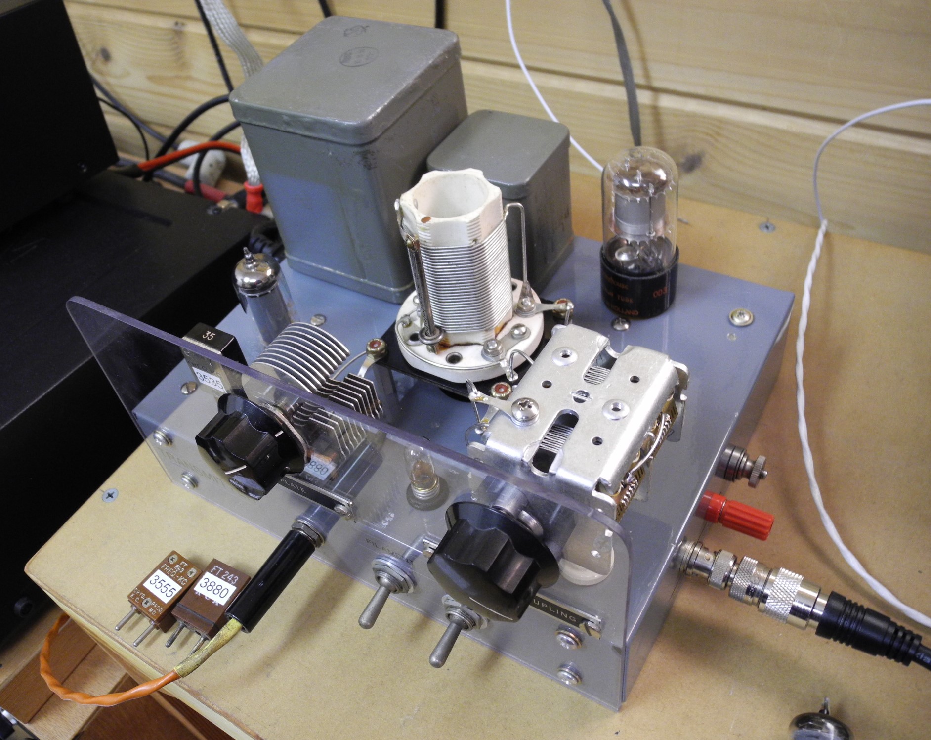
| Top View: In this top view of Tom's transmitter the plate tuning capacitor is on the left and the plate loading capacitor is on the right. As in other versions of the transmitter, Tom used a variable capacitor for the loading capacitor, rather than a group of switched capacitors, as in my transmitter. The variable capacitor is preferred. The power transformer is at the left in the back, and the filter choke is to its right. Both were salvaged from a 1950's URM 25D signal generator. The 0D3 regulator tube is on the right in the back, and the 6CL6 is on the left in the front, to the left of the plate tuning capacitor. The antenna connection can be seen at the right in the photo. Tom used a BNC connector for the antenna rather than an SO-239. Either will work fine. In the middle of the chassis in the front Tom has a #41 6 volt bulb connected in series with the plate transformer center tap. This gives a visual indication of the 6CL6 cathode current. However, the cathode current does not dip at resonance in this transmitter, as it does in many other transmitters. This is because of the presence of the VR tube in the circuit. In fact, the cathode current increases slightly at resonance. (The bulb gets slightly brighter at resonance.) |

Click on the image for a larger view. Click here for a super detailed view. |
In November of 2005 Dave Rogers (WB4CHK) finished building his 6CL6 transmitter and was kind enough to send me some photos. I thought it would be helpful to show how someone else put the transmitter together. If you have any questions for Dave, you can e-mail him at Davewb4@aol.com
| Front View: In this front view of Dave's transmitter, you can see that his front panel layout is essentially the same as the original transmitter layout. The only difference is that Dave mounted the crystal socket horizontally, whereas it is mounted vertically in the original version of the transmitter. (Note: In this photo Dave has the plate tuning and loading control labels reversed. The one marked "plate tuning" should be marked "plate loading" and vice-versa.) |
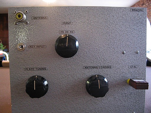 Click on the image for a larger view. Click here for a super detailed view. |
| Rear View: This is the rear view of Dave's transmitter. The layout is similar, but not identical, to that of the original transmitter. You will notice that Dave chose to mount the power supply on a separate chassis, which gives you more room on the transmitter and makes the wiring easier. Dave also made good use of terminal strips for the power supply connections. For the tank coil, Dave used 1 1/4" PVC pipe, and it looks like it worked great.. Dave made his transmitter for 40, 30, and 20 meters, so there are fewer turns of wire and fewer taps on the coil. Another important difference is that Dave used a variable capacitor (on the right in the photo) for the loading capacitor, rather than switched, fixed, capacitors, as in the original. The variable capacitor is definitely the way to go! The large 18pf-500pf capacitor that Dave used (because that is what he had) will work fine, though it is not necessary. A smaller one would do nicely too. Any air variable capacitor with a maximum capacity of 200pf to 400pf should work fine as a loading capacitor. |

Click on the image for a larger view. Click here for a super detailed view. |
| Power Supply: Though Dave chose to use a separate chassis for the power supply, his component layout is very similar to that of the original transmitter. Keeping to tradition, Dave used a bread loaf pan for the chassis, a practice common in the 50's and 60's. At the left rear you can see the black terminal strip that Dave used to make connections to the power supply. The terminal strip is a great idea, as it allows the power supply to be easily used to power other vintage projects. |
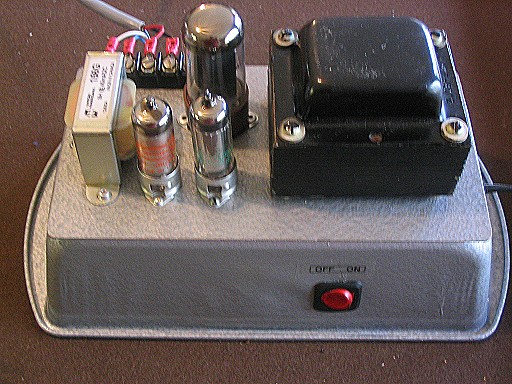
Click on the image for a larger view. Click here for a super detailed view. |
In February, 2008 I received an email from from Charlie Zarek (W9SAY) describing his version of the transmitter. Charlie mounted his transmitter in a wooden case, and designed the transmitter to run off of a generic power supply he has in his shack. If you have questions for Charlie you can e-mail him at w9say@yahoo.net
| Charlie Zarek's (W9SAY) Transmitter: In Charlie Zarek's version of the transmitter the power supply is built on a separate chassis but the voltage regulator tubes are mounted with the transmitter. Charlie used a wooden chassis for his transmitter with a black top panel. Charlie's transmitter is also a single band (40m) transmitter. This simplifies construction. RCA connectors were used for the key and antenna. The power supply connects to the transmitter via the Jones connector right behind the 6CL6. |
 Click on the image for a larger view. Click here for a super detailed view. |
In May of 2015 I received pictures and other information from Tom Valenti
(K3AJ) on his version of the 6CL6 transmitter. Tom modified the transmitter by
using solid state diodes for the power supply rectifier and zener diodes
(Mouser part number 78-BZX85B36) for the voltage regulator tubes.
Tom was kind enough to include a Word file with
lots of information on his version of the transmitter.
He also included a PDF file with the
schematic diagram for his version of the transmitter.
If you have any questions for Tom you can contact him at
tomk3aj@gmail.com
| Front View: Tom used an aluminum chassis for his transmitter. It is very much like that used in a 6AG7 transmitter that appeared in the 1955 ARRL handbook many years ago. It is a beautiful chassis as you can see in the photo. Tom's transmitter has 510V on the tube plate, and therefore puts out 6W, a little more than my transmitter. The 6CL6 is a rugged tube and can handle the 510V, but I don't think I would try to use much more. Note how Tom used an octal plug/tube base and a piece of plastic plumbing pipe for his coil. |
 Click on the image for a larger view. Click here for a super detailed view. |
| Bottom View: Tom used solid state diodes in the power supply instead of the 5Y3 rectifier tube and a string of six 36V zener diodes to replace the voltage regulator tubes. Tom mounted the power supply components on a piece of yellow perf board as can be seen at top center in this photo. The zener diodes (Mouser part number 78-BZX85B36) run down the left side and bottom of the perf board, and the rectifier diodes (2-1kV PIV diodes in series for each side of the transformer secondary) are at the bottom right corner of the perf board. The white resistors in the middle of the photo are the dropping resistors for the zener diodes. Tom included a Word file with lots of information on his version of the transmitter. He also included a PDF file with the schematic diagram. |
 Click on the image for a larger view. Click here for a super detailed view. |
Dave Kirk (W6MQI) sent me information and pictures of his version of the 6CL6 transmitter in August of 2015. Dave used parts from a scrapped Drake 2B receiver as the basis for his transmitter. He used the case from the receiver as well as the power transformer. He also included a transmit/receive system that would switch the antenna, mute his 2B receiver, and, if needed, key an amplifier. He also included a switch for two crystals and a VFO input. All in all, quite a canoe...
| Front View: Dave used the case from a scrapped Drake 2B receiver to house his transmitter. It makes a very nice match to his 2B receiver. Since he had plenty of room in that case, He also included a transmit/receive system that would switch the antenna, mute his 2B receiver, and, if needed, key an amplifier. He also included a switch for two crystals and a VFO input. |
 Click on the image for a larger view. Click here for a super detailed view. |
| Bottom View: Dave's chassis is plywood clad with copper. Very sturdy construction. He used solid state diodes instead of a tube rectifier, and used zener diodes in place of the voltage regulator tubes. This is strictly a matter of personal taste. Dave used coaxial cable to make the connections between the crystal socket and tube socket. I don't recommend this because the cable capacitance can load down the circuit and cause sluggish starting/keying with some crystals. The connections between the crystal socket and tube socket should be as short as possible. Any cable between the VFO input and tube socket should also be as short as possible to minimize the effect of the cable capacitance. The extra cable capacitance can shunt the VFO output and lessen the drive to the tube. |
 Click on the image for a larger view. Click here for a super detailed view. |
| Rear View: Is this photo from the rear of the transmitter, you can see how Dave laid out the top of the chassis. The loading capacitor is at left, and the plate tuning capacitor is at the upper right. Dave used flexible insulated couplings and panel bearings on the shafts of these capacitors. The couplings allow the shafts to flex, and provide for a very nice feel. Straight uninsulated shaft couplings are fine if you can't find or afford the insulated couplings. The panel bearings can be omitted too if you don't have them, but they sure make the tuning smoother if you use them. Dave's tank coil can be seen at the top. Note the beautiful job Dave did on winding this coil. Also note how he has kept the connections between the coil and the bandswitch (on the front panel) as short as possible. The Drake 2B power transformer is more than adequate to power the transmitter. This is a great way for it to see a second life. The crystal socket can be seen just above the power transformer. This could, perhaps, have been mounted closer to the tube socket. See my earlier comments on keeping the connections between the crystal and the tube as short as possible. The power supply filter choke can be seen at the bottom to the right of the transmit/receive system relays that Dave included with his design. |
 Click on the image for a larger view. Click here for a super detailed view. |
| Back View: Dave has a clean, well arranged back panel on his transmitter. He used BNC connectors for many of the connections. These provide for solid, worry free connections to the transmitter. If you don't have BNC connectors or find them hard to work with, RCA phono connectors are fine for all of these connections. If desired, a standard SO-239 UHF connector could also be used for the antenna connection. |
 Click on the image for a larger view. Click here for a super detailed view. |
 Click here for pictures and information on the Wingfoot
VFO 2E26 Exciter
Click here for pictures and information on the Wingfoot
VFO 2E26 Exciter Click here for pictures and information on the Wingfoot
813 Amplifier
Click here for pictures and information on the Wingfoot
813 Amplifier Back to Dr.
Greg Latta's Electrical Engineering and Amateur Radio Pages
Back to Dr.
Greg Latta's Electrical Engineering and Amateur Radio Pages
 If you have any questions or
comments, you can send E-Mail to Dr. Greg Latta at
glatta@frostburg.edu
If you have any questions or
comments, you can send E-Mail to Dr. Greg Latta at
glatta@frostburg.edu
This page is under constant revision. Please check back often.