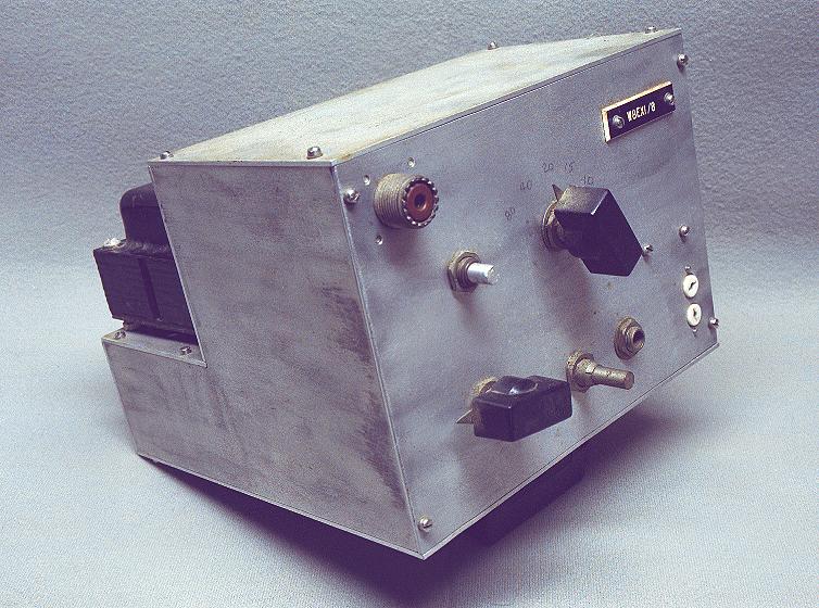
| Original Condition - Front View: This is a picture of the front of the transmitter as it was originally received from Jim Trutko, W8EXI. Knobs are missing, and the band switch positions are simply written in pencil on the front panel. A yellowish tinge covers the entire transmitter. |
Click on the image for a larger view. Click here for a super detailed view. |
| Original Condition - Straight-On Rear View: Well, I think this photo summarizes the poor original condition of the transmitter. What a mess! Corrosion is present just about everywhere: on the elctrolytic capacitor, the chassis, and even the transformer mounting bolts. The transformer is mounted cock-eyed on the chassis, and the chassis itself is warped. What you can't see in this photo (but you can see in the bottom photo) is that underneath none of the power supply components are wired! They are simply mounted on the chassis with no connections to them. |
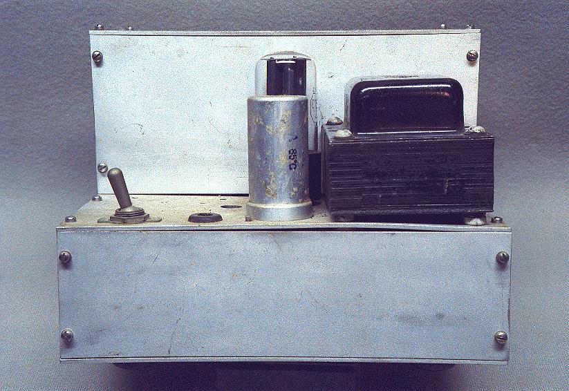 Click on the image for a larger view. Click here for a super detailed view. |
| Original Condition - Angled Rear View: In this angled rear view the yellowish tinge that covers the transmitter is very visible. Despite the dirt and other problems, there are definite possibilities. The power transformer alone is worth its weight in gold. Power transformers for tube circuits are expensive and hard to come by nowadays. Compare these photos to those of the finished transmitter. |
 Click on the image for a larger view. Click here for a super detailed view. |
| Original Condition - Complete Bottom
View: This is a a full bottom view of the transmitter in its original condition. Notice that none of the power supply components are wired. There is also a big rat's nest of wiring around the turret assembly at the top right. The transformer leads are quite short in some cases, and will need to be lengthened. |
 Click on the image for a larger view. Click here for a super detailed view. |
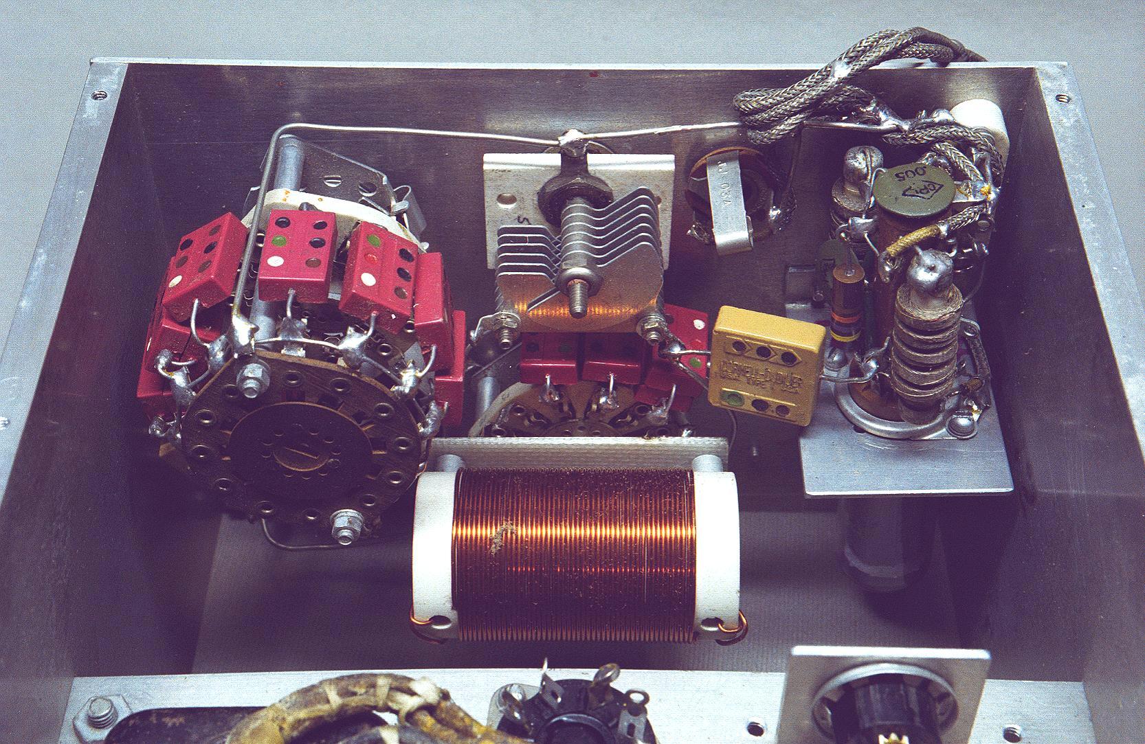
| Original Condition - Angled Bottom View: In this angled bottom view the rat's nest of wiring around the turret assembly at the right is clearly visible. A close look at the bandswitch in the middle of the photo will also show the postage stamp padding condensers wired to the switch that were used to pad the plate loading capacitor. These were wired incorrectly and turned out to be unnecessary. They are not present in the finished transmitter. The key jack is visible crammed in between the plate tuning capacitor at top center and the turret assembly on the right. When the new front panel was machined the key jack was moved to a place between the loading capacitor switch assembly and the output connector, which is not visible in the photo. |
 Click on the image for a larger view. Click here for a super detailed view. |
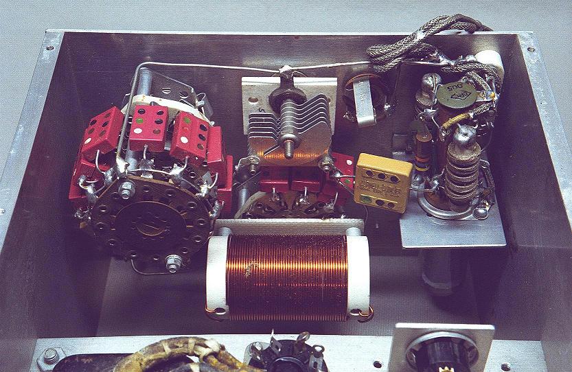
| Original Condition - Top View With Cover Removed: This is another photo that really shows the corrosion and filth that originally covered the transmitter. At bottom right a wirewound pot is visible mounted to the front panel. This served no purpose and is not present in the finished transmitter. The electrolytic capacitor on the left above the power transformer turned out to be leaky and had to be replaced. The power supply panel that the rectifier tube and power transformer are mounted on was machined to accept the filter choke and VR tubes, and was reused in the finished transmitter. |
 Click on the image for a larger view. Click here for a super detailed view. |
 Click here for pictures and information on the Wingfoot
VFO 2E26 Exciter
Click here for pictures and information on the Wingfoot
VFO 2E26 Exciter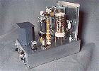 Click here for pictures and information on the Wingfoot
813 Amplifier
Click here for pictures and information on the Wingfoot
813 Amplifier Back to Dr.
Greg Latta's Electrical Engineering and Amateur Radio Pages
Back to Dr.
Greg Latta's Electrical Engineering and Amateur Radio Pages
 If you have any questions or
comments, you can send E-Mail to Dr. Greg Latta at
glatta@frostburg.edu
If you have any questions or
comments, you can send E-Mail to Dr. Greg Latta at
glatta@frostburg.edu
This page is under constant revision. Please check back often.